Dataflow Part 4 - The Linux Routes Table
Assumptions
- You have a CF deployed with at least 2 diego cells
- You have two proxy apps pushed and named appA and appB (the fewer apps you have deployed the better)
Review
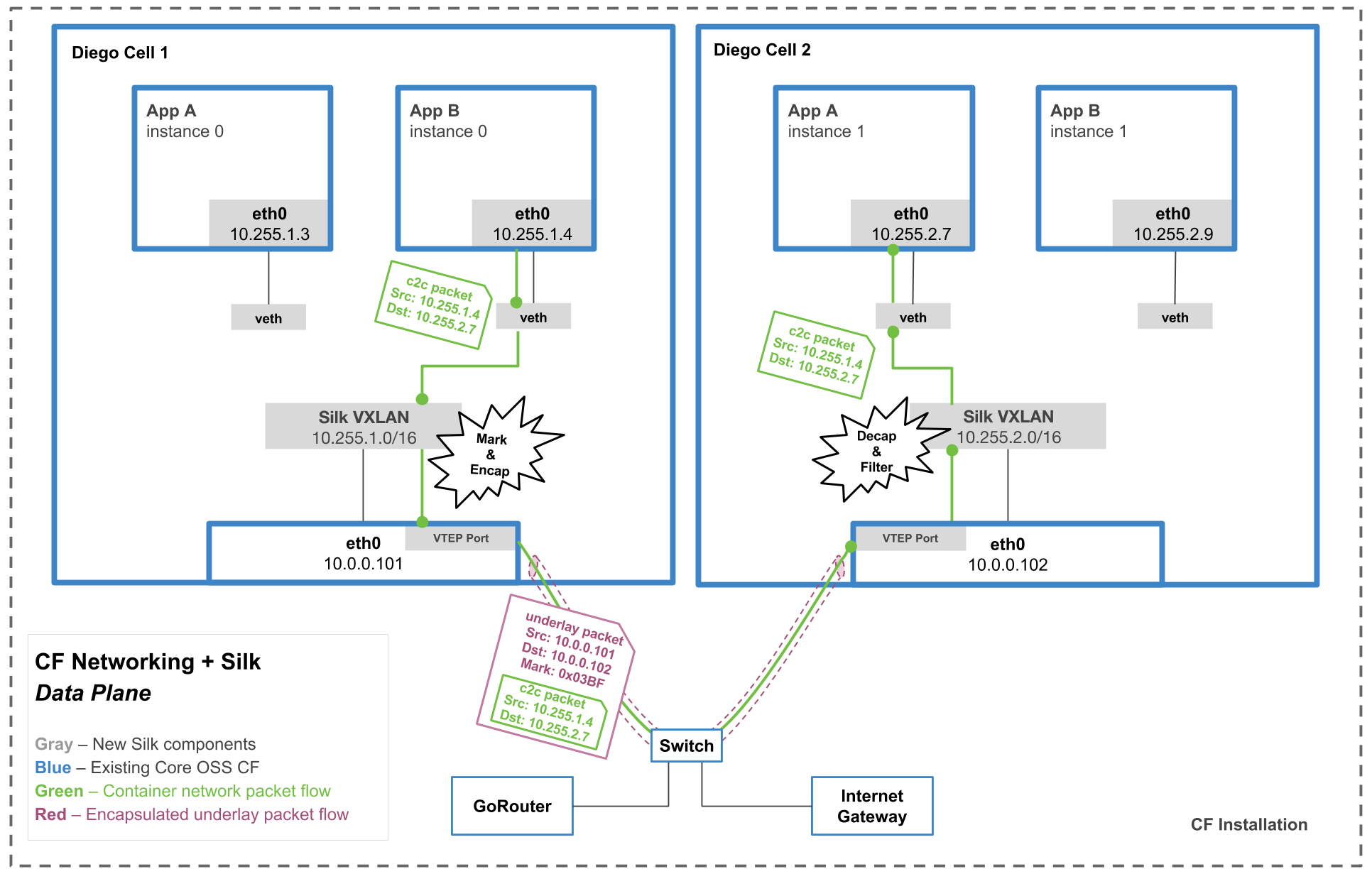
This track of stories is going to go through the steps (listed below) that were covered in the dataflow overview. The steps and diagram will be at the top of each story in case you need to orient yourself. Higher quality diagram here.

- AppB (on Diego Cell 1) makes a request to AppA’s overlay IP address (on Diego Cell 2). This packet is called the overlay packet (aka the c2c packet).
- The packet exits the app container through the veth interface.
- **The overlay packet is marked with a …mark… that is unique to the source app.
- Because the packet is an overlay packet, it is sent to the silk-vtep interface on the Diego Cell. This interface is a VXLAN interface. <——- CURRENT STORY
- The overlay packet is encapsulated inside of an underlay packet. This underlay packet is addressed to underlay IP of the Diego Cell where the destination app is located (appA in this case).
- The underlay packet exits the cell.
- The packet then travels over the physical underlay network to the correct Diego Cell.
- The packet arrives to the correct Diego Cell
- The underlay packet is decapsulated. Now it’s just the overlay packet again.
- Iptables rules check that appA is allowed to talk to appB based on the mark on the overlay packet.
- If traffic is allowed, the overlay network directs the traffic to the correct place.
What
In order for all overlay packets to be sent to the correct interface, the linux routes table needs to be configured correctly. But, what is a linux routes table?
How
🎥 Watch this video “Routing Tables Explained” length 7:35.
Expected Outcome
You understand the basics of a route table.