Dataflow Overview
What
In the last story you learned the difference between underlay networks (physical) and overlay networks (software).
Let’s see how both the overlay and underlay networks are used when one app talks to another using container to container networking (c2c).
Each step marked with a ✨ will be explained in more detail in its own story.
How
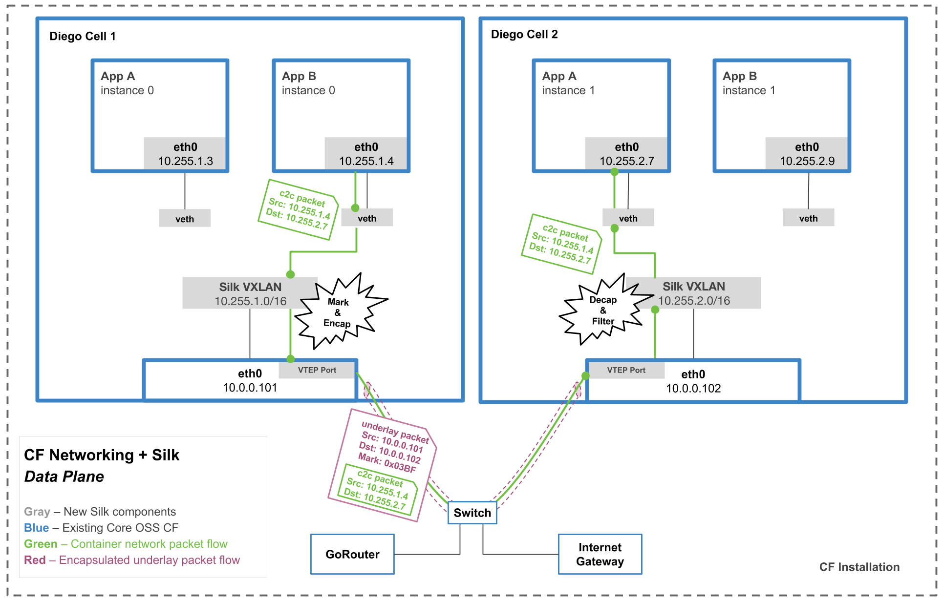
Follow the steps below on the diagram. (Higher quality diagram here.)

Note: There are a lot of new terms below: “veth”, “VTEP”, “VXLAN”, etc. Feel free to google if you need to know now, but if not, hang tight. We’ll unpack these terms more in the stories that follow.
Container-to-container networking dataflow step by step
- AppB (10.255.1.4) makes a request to AppA’s overlay IP address (10.255.2.7). This packet is called the overlay packet (aka the c2c packet).
- ✨ The packet exits the app container through the veth interface.
- ✨ The overlay packet is marked with a …mark… that is unique to the source app.
- ✨ Because the packet is an overlay packet, it is sent to the silk-vtep interface on the Diego Cell. This interface is a VXLAN interface.
- ✨ The overlay packet is encapsulated inside of an underlay packet. This underlay packet is addressed to underlay IP of the Diego Cell where the destination app is located (appA in this case).
- The underlay packet exits the cell.
- The packet then travels over the physical underlay network to the correct Diego Cell.
- The packet arrives to the correct Diego Cell
- The underlay packet is decapsulated. Now it’s just the overlay packet again.
- ✨ Iptables rules check that appA is allowed to talk to appB based on the mark on the overlay packet.
- If traffic is allowed, the overlay network directs the traffic to the correct place. Yay!
Expected Result
You should have a basic overview of the data path for container to container networking…even if you don’t understand it all yet. The next few stories will go through and explain each of the steps marked with a ✨.